Enforcement Boundaries
In the Illumio Segmentation for Data Centers 21.2.0 release, Illumio introduces Enforcement Boundaries, a new feature to speed your journey toward Zero Trust.
The Journey Toward Zero Trust
The Illumio security policy model is based on the principle of Zero Trust. What is Zero Trust? Zero Trust security segments internal networks and prevents the lateral spread of ransom ware and cyber breaches. When implemented, it eliminates automatic access for any source – internal or external – and assumes that internal network traffic cannot be trusted without prior authorization.
Achieving Zero Trust security is possible with the Illumio Segmentation for Data Centers because it bases security policy on an allowlist model. The allowlist model means that you must specifically define what traffic is allowed to communicate with your managed workloads; otherwise, it is blocked by default. It follows a trust-centric model that denies everything and only permits what you explicitly allow—a better choice in today’s data centers. The list of what you do want to connect in your data center is much smaller than what you do not want to connect.
From a security perspective, creating policy based on allowlists is the preferred method and has the advantage of specifying what you trust explicitly; however, creating security policy exclusively on the allowlist model has some disadvantages. To start enforcing policy using the allowlist model, you must have a clear and complete understanding of all network communication within your data center. Accounting for all the connections that must be allowed between your hosts and applications is important or you risk business-critical applications breaking. Without this perfect knowledge, you either leave holes in your security, or you block necessary connections that break application functionality.
Approaches toward Reaching Zero Trust
Implementing allowlist security in a greenfield environment is much easier because your knowledge of application connection requirements is current and your application developers can define allowlist policy (rules) as part of the application deployment.
In a brownfield environment, applications are already deployed and running. A data center can have thousands of applications. How do you go about deploying an allowlist model into a brownfield environment? Often, Illumio Segmentation for Data Centers customers implement allowlist security in a brownfield environment by creating security policy one application at a time. By default, the PCE sets the enforcement state to “visibility only” when you install a VEN on a host, thereby allowing you to assess what traffic is reaching the host. You can observe application behavior in reaction to potential security policy, and gradually move applications into full enforcement.
This approach can be very successful in achieving Zero Trust for your environment. However, it can lack the ability to accommodate unplanned security mandates, such as blocking a new security threat, or limiting traffic between corporate headquarters and a new business location.
So, how do you compensate between these two competing goals? Requiring a complete understanding of your data center versus being agile enough to tackle sudden security mandates? The solution is to introduce a new set of rules that determine where rules apply. These rules are referred to as Enforcement Boundaries in Illumio Segmentation for Data Centers. Enforcement Boundaries can block traffic from communicating with workloads you specify, while still allowing you to progress toward a Zero Trust environment.
Enforcement Boundaries: How They Work
Enforcement Boundaries provide the following advantages:
Unlike firewall policies, boundaries provide a simple policy model that does not depend on rule order.
Boundaries facilitate a secure path to block traffic to achieve a Zero Trust model.
Enforcement boundaries are separate from allowlist rules. You can use multiple labels in a boundary or specify a label group. They are not limited by label types. Enforcement boundaries can be applied across a set of workloads, ports, and IP addresses.
You can create an Enforcement Boundary between workloads running different operating systems. When you use the existing Illumio Segmentation for Data Centers RAEL labels to designate workloads by OS, creating an Enforcement Boundary by OS is possible.
You can combine Enforcement Boundaries with allowlist rules in your overall security policy. Allowlist rules always supersede Enforcement Boundaries. For example, you might have a server running a legacy NetBIOS file. This server is deployed in your development environment and must communicate with an application running in your production environment. You have already created an Enforcement Boundary blocking traffic between workloads in the development and production environments. You workaround this requirement by creating a specific rule allowing NetBOIS traffic to connect through the ports on the production server.
Summing It All Up
Enforcement Boundaries are…
Part of the Illumio declarative policy model.
You define the end state and Illumio Segmentation for Data Centers creates the appropriate native firewall rules. You don't have to worry about rule order. In the traditional firewall, you do.
Overridden by allowlist policy.
Directional; you can create Enforcement Boundaries that are source-centric or destination-centric.
For example, you want to block traffic from one location but only in one direction.
Flexible; they are available for label groups and IP lists.
Most often used for brownfield deployments.
Intended to serve as a stepping stone towards a full traditional allowlist policy model.
Implementing Enforcement Boundaries allow you to start the path toward full enforcement without having full knowledge of your data center environment.
Use Cases for Enforcement Boundaries
Potential use cases for Enforcement Boundaries include:
Environmental or location separation and individual service enforcement.
For example, you want to reduce risk in your environment by blocking traffic between your development and production environments.
You want to control which locations or entities in your environment that can communicate. For example, you organization just acquired another entity and you want to block network traffic between the two locations.
Blocking traffic from specific services from traversing your network; such as:
Unencrypted protocols like unencrypted HTTP traffic unless explicitly allowed to a host.
Ubiquitous services in your network; for example, you don't want to allow Telnet access anywhere in your network.
Examples: Ways to Deploy
The following examples illustrate some common ways to utilize Enforcement Boundaries.
Block Traffic Between Environments
In the following example, an IT organization receives a mandate to implement security policy between the workloads in the development and production environments on a fixed project time line. Approaching this with a Zero Trust model could push implementation past the deadline. Achieving this security goal by using an Enforcement Boundary is achievable. It requires primarily two tasks: deploy VENs on all the workloads and set the Environment label correctly.
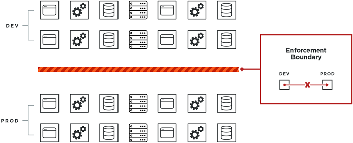
In this example, the IT organization can effectively block traffic between these two environments without requiring a complete picture of all port and protocol requirements for all applications or hosts in the production environment. No applications are at risk of breaking in production because required traffic was inadvertently blocked between applications or hosts in production.
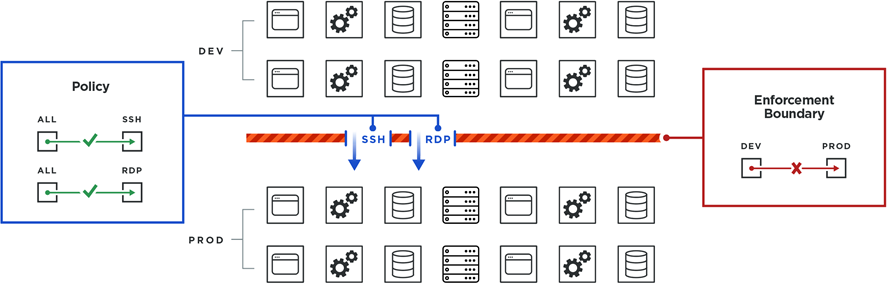
Allowed Traffic Supersedes Enforcement Boundary
In this example, you can still allow instances of services to communicate with the production environment. Any policy that you create (the allowlist model) that allows a service to reach applications or hosts running in production still works and the rule will override the Enforcement Boundary. You explicitly create a rule that allows the SSH and RDP services to reach the necessary workloads.
SSH and RDP traffic can reach workloads in production without breaking the boundary blocking traffic from development workloads to production.
Add an Enforcement Boundary
Add an Enforcement Boundary
From the PCE web console menu, choose Enforcement Boundaries.
Click Add.
The Create Enforcement Boundaries page appears.
Enter a name for the Enforcement Boundary. Names can contain up to 255 characters.
Specify the destinations and providers of the connection. For a definition of “providers” and “destinations,” see Rules.
In the Providing Services field, select services to block or select Port or Port Range and enter the port numbers.
The drop-down list contains a list of all services you have created in the PCE. See Services for the steps to add services to the PCE.
Tip
When selecting a providing service, you can select a specific service (or set of services) from the drop-down list. Alternatively, you can select “All Services” from the drop-down list; effectively blocking all traffic from the traffic source. For example, you might want to block all traffic from your development environments reaching production and you'd select “All Services” for that Enforcement Boundary. See the example below.
Click Save. A progress bar appears while the PCE saves the boundary.
After you save a new Enforcement Boundary, the PCE calculates the impact of the new boundary and the PCE web console page refreshes to display the Blocked tab for that boundary.
The Blocked Connections tab lists all the traffic that crosses the new boundary. See Review Traffic Blocked by a Boundary and Add Rules for the steps to complete the Enforcement Boundary creation workflow.
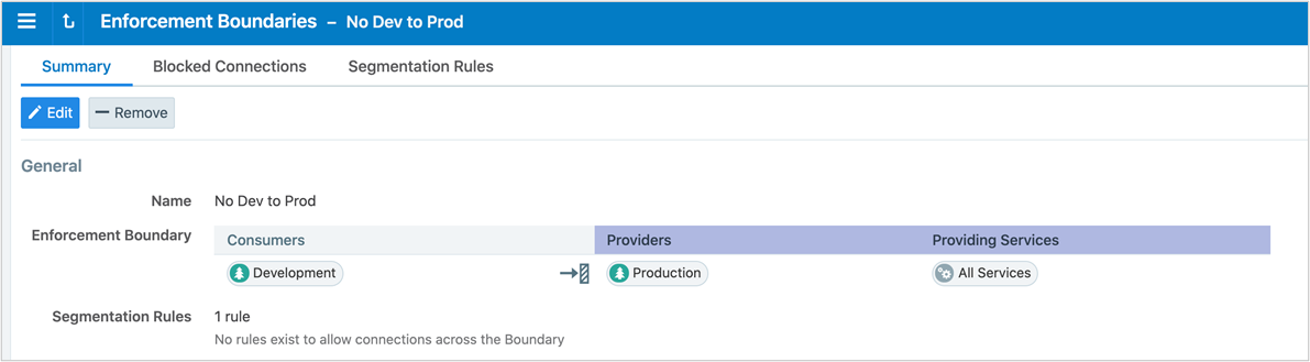
Example: Summary page for an Enforcement Boundary that blocks traffic between development and production
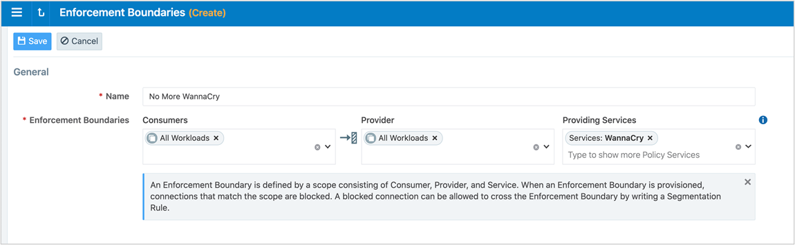
Example: Enforcement Boundary that blocks traffic originating from the WannaCry service
The following boundary blocks communication for the four ports that are part of the WannaCry service for all workloads from all the workloads.
Review Traffic Blocked by a Boundary and Add Rules
When you add an Enforcement Boundary in the PCE for your managed environment, that boundary can affect large amounts of workloads (assuming all those workloads are in Selective Enforcement state.) Therefore, Illumio recommends you use care to not break any applications that have traffic that currently traverses the new boundary.
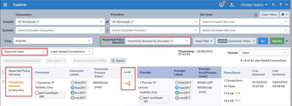
View Traffic Blocked by Boundary in Explorer
The Reported and Draft views of Explorer display traffic blocked by Enforcement Boundaries. You can distinguish when Enforcement Boundaries are blocking traffic from Explorer and use it for troubleshooting.
In particular, you can view information in Explorer about Enforcement Boundaries and where allowed traffic passes through a boundary:
In selective enforcement, you can see whether traffic flows are blocked by Enforcement Boundaries.
In full enforcement, you can see whether traffic flows are blocked by Enforcement Boundaries.
In visibility only mode, you can see whether traffic flows are potentially blocked by Enforcement Boundaries.
Additionally, you can filter traffic flows that are blocked by Enforcement Boundaries in both Draft and Reported views.
Note
The ability to pinpoint the exact allow rule that is blocked by an Enforcement Boundary is not supported in the Explorer Reported view. To view this information, switch to the Draft view of Explorer. In Draft view, you can locate the allow rule blocked by an Enforcement Boundary.
View Blocked Connections in Enforcement Boundary Page
To help evaluate traffic that traverses the boundary, the PCE web console includes a tab for blocked traffic on the Boundary page. This tab essentially runs an Explorer query that returns all the traffic that would be blocked once you provision the new Enforcement Boundary.
Important
After you save a new Enforcement Boundary, the PCE calculates the impact of the new boundary and the PCE web console page refreshes to display the Blocked Connections tab for that boundary. At this point in the boundary creation workflow, you should review the list of traffic that currently crosses the new boundary and determine which connections need exceptions to the boundary. You can also perform this task for existing Enforcement Boundaries at anytime.
To review traffic blocked by a new boundary and add rules for exceptions:
From the Enforcement Boundary Blocked Connections page, review the list of traffic that traverses the boundary and requires an exception to the boundary.
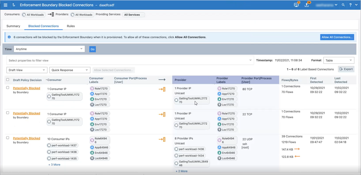
The PCE creates default rules for this traffic that currently traverses the Enforcement Boundary.
To accept the default rules created by the PCE, click the Allow All Connections button after reviewing the list of traffic flows traversing the boundary.
Note
If you have more than 50 traffic flows blocked by the boundary so that the list of connections spans multiple pages in the PCE web console, clicking Allow All Connections accepts the rules in all pages.
To review and accept rules for only specified traffic flows, select their check boxes and click the Allow Selected Connections button.
The page refreshes and displays the proposed rules to create exceptions to the Enforcement Boundary. All new rules display the status “Addition Pending” in the Provision Status column.
To modify and optimize the proposed rules for traffic traversing the boundary, click the pencil icon at the end of the row for the rule you want to optimize. The values for that row become editable. Make changes to the rule as needed and click the Save icon.
For example, you might want to collapse rules for similar protocols into one rule. When you collapse two rules into one, the PCE automatically removes the original duplicate rule.
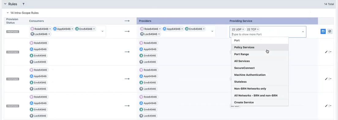
When you are done reviewing and optimizing the proposed rules, click the Save button at the top of the page.
The page refreshes and the Rules tab for the Enforcement Boundary appears. All rules that will traverse the boundary are listed.
To provision all pending policy changes, click the Provision button at the top of the page. The provisioning process begins.
See Provisioning for information.
Disable an Enforcement Boundary
You can temporarily disable an enforcement bounday, such as for troubleshooting. You can enable it again when needed.
From the PCE web console menu, choose Enforcement Boundaries.
Select one or more enforcement boundaries you want to disable.
Click Disable.
The status of the enforcement boundary changes to Disabled.
When you are ready to enable the enforcement boundary again, select it and click Enable.
Remove an Enforcement Boundary
From the PCE web console menu, choose Enforcement Boundaries.
Select the enforcement boundary you want to remove.
Click Remove.
A confirmation dialog box appears.
Click Remove again to permanently delete the enforcement boundary from the PCE.
The Enforcement Boundaries page reappears. An icon appears beside the enforcement boundary indicating that the deletion is pending.
Provision the change. See Provisioning for information.