Configure Flowlink
This topic describes how to configure Flowlink.
You configure Flowlink using a YAML file that defines its runtime behavior, while an included JSON schema validates the configuration to ensure all parameters are complete, well‑formed, and supported. When FlowLink starts (or restarts), it automatically validates the YAML against the JSON schema.
If validation succeeds:
FlowLink parses flows according to the configured consumers.
Aggregates them on the defined interval.
Posts them to the PCE using the provided credentials.
If validation fails:
FlowLink logs explicit configuration errors.
No data is ingested or sent.
STEP 1: Install the Flowlink RPM
Log in as a root user.
Install the RPM.
The default install location is:
/usr/local/bin/Standard installation:
sudo su rpm -ivh illumio-flowlink-x.x.x-yy.x86_64.rpmImportant
Only the Install Flowlink RPM step requires root user login.
Illumio users logged in with any role can perform the steps in STEP 2: Create a Service Account API Key, Create YAML Configuration File, and Run Flowlink.
In the following sections, /home/employee directory is used as an example. The api_info file should be in a directory writable by the user, for example in the /home/employee directory.
STEP 2: Create a Service Account API Key
There are two ways to create a Service Account API key for Flowlink:
Through the API. See API Keys.
Through the PCE Web Console (described in the procedure below).
The Org ID value is not shown when you create a Service Account API key.
Service accounts are always organization-based and specific to a PCE. While creating a service account, users create their permissions and an
api_keyis created implicitly. Deleting a service account removes its permissions and all associated API keys.
In the PCE UI, go to Access > Service Accounts.
Click Add and configure settings.
Name
Description (optional)
Access Restriction: None.
API Key expiration: Keep the default or choose a different option.
Roles and Scopes: Select Global Administrator. The All is chosen automatically and cannot be changed.
Click Save.
When the API Key Created dialog appears, preserve the credentials (make a note or download them).
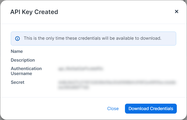
Copy the values of the Authentication Username and Secret into to a text file on the Flowlink server.
Use a space to separate the key and secret. For example:
api_xxxxxxxxxxxxxx yyyyyyyyyyyyyyyyyyyyyyyyyyyyyyyyyyyyyyyyyyyyyyyyyyyCopy the absolute path of the file PCE API file
/home/employee/api_info. You will need it in the Flowlink configuration file.
STEP 3: Configure HTTP/HTTPS Proxy (if needed)
Important
Perform this step only when FlowLink is isolated from the internet and needs to use a proxy to access the PCE.
Supported on Flowlink 1.3.0 and later.
When Flowlink is running behind a proxy or in a corporate network and the PCE is in the cloud, Flowlink can access the PCE via HTTP/HTTPS proxy configurations.
The following configuration parameters are available to define an HTTP/HTTPS proxy:
proxy_config:
  https_proxy: <HTTPS_PROXY>
  http_proxy: {} <HTTPS_PROXY>{}
The following is an example of a Flowlink YAML configuration file:
proxy_config:
  https_proxy: http://proxy.corporate.com:3128
  http_proxy: http://proxy.corporate.com:3128
In the example above, the HTTP/HTTPS proxy is running on FQDN proxy.corporate.com{{ port: 3128}}.
STEP 4: Configure a Flowlink YAML File
Configure Flowlink by defining its runtime parameters in a YAML file. The included JSON schema validates the configuration to ensure all parameters are complete, well‑formed, and supported.
Note
Refer to the /usr/local/illumio/flowlink_config_schema.json file provided with the Flowlink RPM for definitions of all the fields supported by the Flowlink YAML configuration file.
In the
/home/employeedirectory, create a YAML configuration file. You can find an example yml file at/usr/local/illumio/config.yml.example.Enter the parameters. (See Flowlink Key-Value Parameters for details).
Example configuration
The following configuration listens for NetFlow on UDP 2055 from any data source. The absolute path is: /home/employee/config.yaml.netflow
pce_addr: mypce.example.com:8443
api_key: $cat /home/employee/api_info
data_directory: /home/employee
aggregation_minutes: 10
consumers:
  - name: netflow
    parser:
      type: netflow
    connectors:
      - type: udp
        properties:
ports: '2055'This table details the key-value parameters in Flowlink's YAML configuration file.
Parameter | Required/Optional | Description |
|---|---|---|
| Optional | The interval (in minutes) in which flows are aggregated and sent to the PCE. Default interval: 10 Minimum allowed interval: 5 Maximum allowed interval: 60 For example:
|
| Required | API key and secret of the PCE. This allows Flowlink to POST flows to the PCE. The API key and secret can be copied into a file. You can run a script to cat the contents of that file. In the example below, a file called api_info is created which contains the PCE API key and secret. For example:
|
| Required | A list of dictionaries. It requires a name, parser, and connector. Flowlink configuration supports one or many consumers (flow types). For more details about configuring the ingested flow types, see Ingested Flow Types. |
| Required | The pathname of a directory where Flowlink can store any unsent data flow files or any restart information. For example:
|
| Optional | The maximum size (in Megabytes) of data that can be stored in the data directory before being pruned. Default: 500 Minimum value: 100 For example:
|
| Optional | The maximum number of hours unsent data flow files will be stored before being pruned. Default: 24 Minimum: 4 For example:
|
| Optional | The frequency (in seconds) at which the metrics information is printed. Default: 60 Minimum: 15 For example:
|
| Required for SaaS Optional for on-premises | The org id to which the flow data will be posted. The default id is 1. For example:
|
| Required | FQDN of the PCE and port. For example:
|
| Optional (unless you're configuring certain integrations (for example, Armis and the PCE)). | Allows you to stream flows to Azure Event Hub (instead of directly to the PCE) for use in Insights and Segmentation, and to configure the parameters included in flow headers. NoteCurrently, this feature is accessible to only a limited number of organizations. Applies to Flowlink 2.0.0 and later: If you are configuring Flowlink as part of an integration with the PCE and Armis, make sure to add the following to your Flowlink YAML file at the root level:
For details, see About the Illumio and Netflow/sFlow Integration. |
STEP 5: Run Flowlink
To manage Flowlink, use the following commands:
illumio-flowlink-ctl start --config <path to config file> [--log-file <path to log file>]
illumio-flowlink-ctl stop
illumio-flowlink-ctl status
The default path for the log file is <data_directory specified in config file>/
flowlink.logTo start Flowlink, use the
illumio-flowlink-ctl startcommand. Make sure that you include the--configoption in the start command, which will begin running the program in the background.Example with expected output:
illumio-flowlink-ctl start --config /home/employee/config.yaml.netflow

OUTPUT TO CONSOLE
Checking Flowlink started successfully.
OK.
Output logs can be found at: /home/employee/flowlink.log

OUTPUT IN LOG FILE (/home/employee/flowlink.log)
2020-03-11T09:58:51.173203-07:00 Waiting for signal
2020-03-11T09:58:51.330757-07:00 Starting Data source: netflow
2020-03-11T09:58:51.331162-07:00 Listening for netflow messages on udp port: 2055
2020-03-11T09:58:51.332929-07:00 Reporting flows every 10 minutes
To stop Flowlink, use the
illumio-flowlink-ctl stopcommand.Example with expected output:
illumio-flowlink-ctl stop

OUTPUT ON CONSOLE
/illumio-flowlink-ctl stop
Stopping Flowlink: ......... Stopped.

OUTPUT IN LOG FILE (/home/employee/flowlink.log)
2020-03-11T09:58:57.097817-07:00 Got signal
2020-03-11T09:58:57.097835-07:00 Telling connectors to stop
2020-03-11T09:58:57.097856-07:00 Allowing parsers to drain
2020-03-11T09:58:57.098766-07:00 udp exiting
2020-03-11T09:58:57.098800-07:00 udp exiting
2020-03-11T09:58:57.101361-07:00 udp exiting
2020-03-11T09:58:57.101400-07:00 udp exiting
2020-03-11T09:58:57.103881-07:00 udp exiting
2020-03-11T09:58:57.103905-07:00 udp exiting
2020-03-11T09:58:57.106527-07:00 udp exiting
2020-03-11T09:58:57.106579-07:00 udp exiting
2020-03-11T09:58:57.109120-07:00 udp exiting
2020-03-11T09:58:57.109145-07:00 udp exiting
2020-03-11T09:58:57.111790-07:00 udp exiting
2020-03-11T09:58:57.111837-07:00 udp exiting
2020-03-11T09:58:57.113853-07:00 udp exiting
2020-03-11T09:58:57.113912-07:00 udp exiting
2020-03-11T09:58:57.116262-07:00 udp exiting
2020-03-11T09:58:57.116397-07:00 udp exiting
2020-03-11T09:58:57.118365-07:00 udp exiting
2020-03-11T09:58:57.119002-07:00 udp exiting
2020-03-11T09:58:57.120865-07:00 udp exiting
2020-03-11T09:58:57.121108-07:00 udp exiting
2020-03-11T09:58:57.123517-07:00 udp exiting
2020-03-11T09:58:57.123552-07:00 udp exiting
2020-03-11T09:58:57.126043-07:00 udp exiting
2020-03-11T09:58:57.126079-07:00 udp exiting
2020-03-11T09:59:02.100923-07:00 Writing flows
2020-03-11T09:59:02.100969-07:00 Flow count: 48468
2020-03-11T09:59:02.417261-07:00 Waiting for file senders to drain
2020-03-11T09:59:02.418564-07:00 Sending file: /home/employee/traffic_flows_1583945942416835.pb.gz
2020-03-11T09:59:07.390307-07:00 Response Code 204
To check the status of Flowlink, use the
illumio-flowlink-ctl statuscommand.Example with expected output:
illumio-flowlink-ctl status

OUTPUT ON CONSOLE
/illumio-flowlink-ctl status
Flowlink: RUNNING